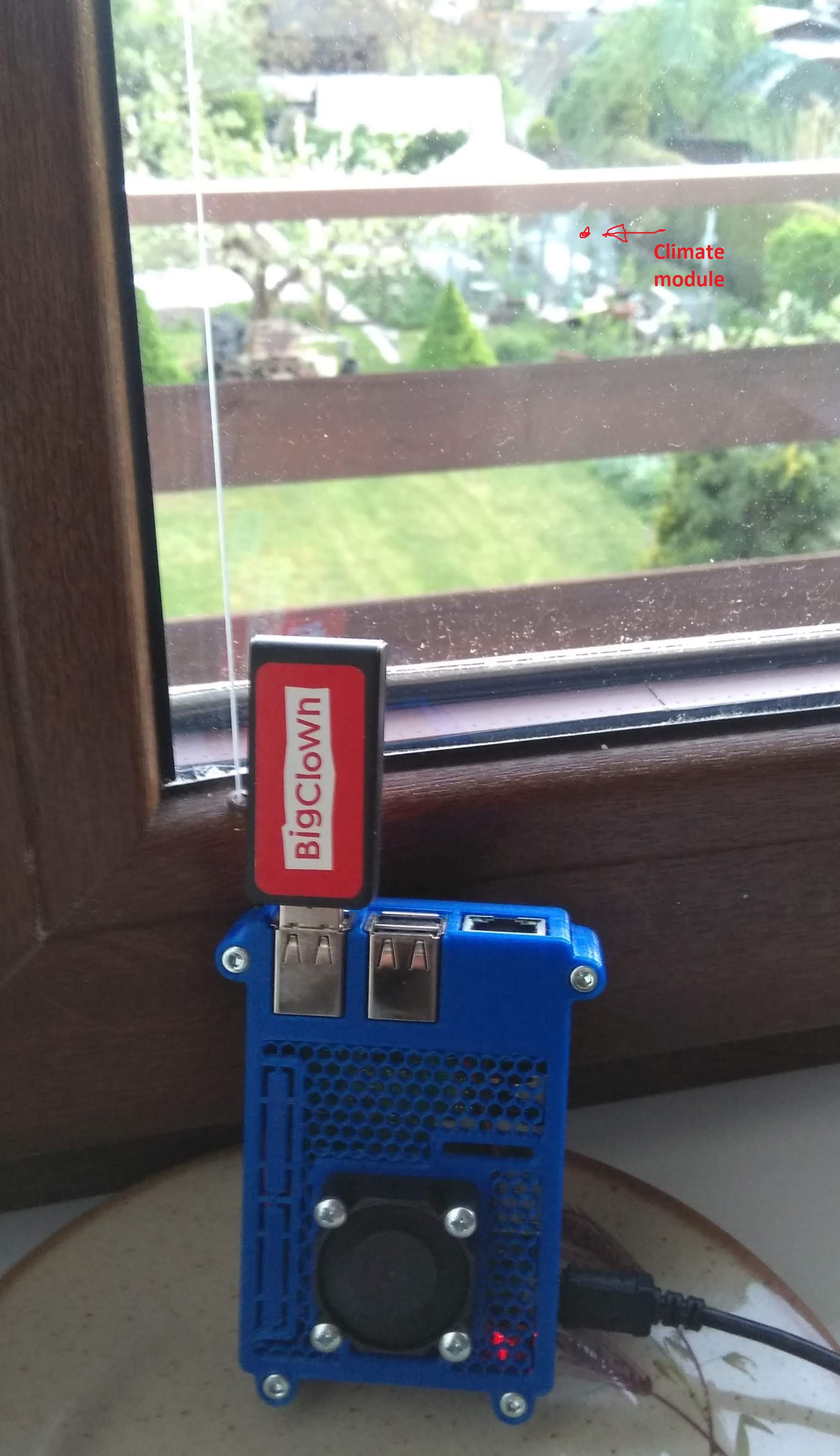
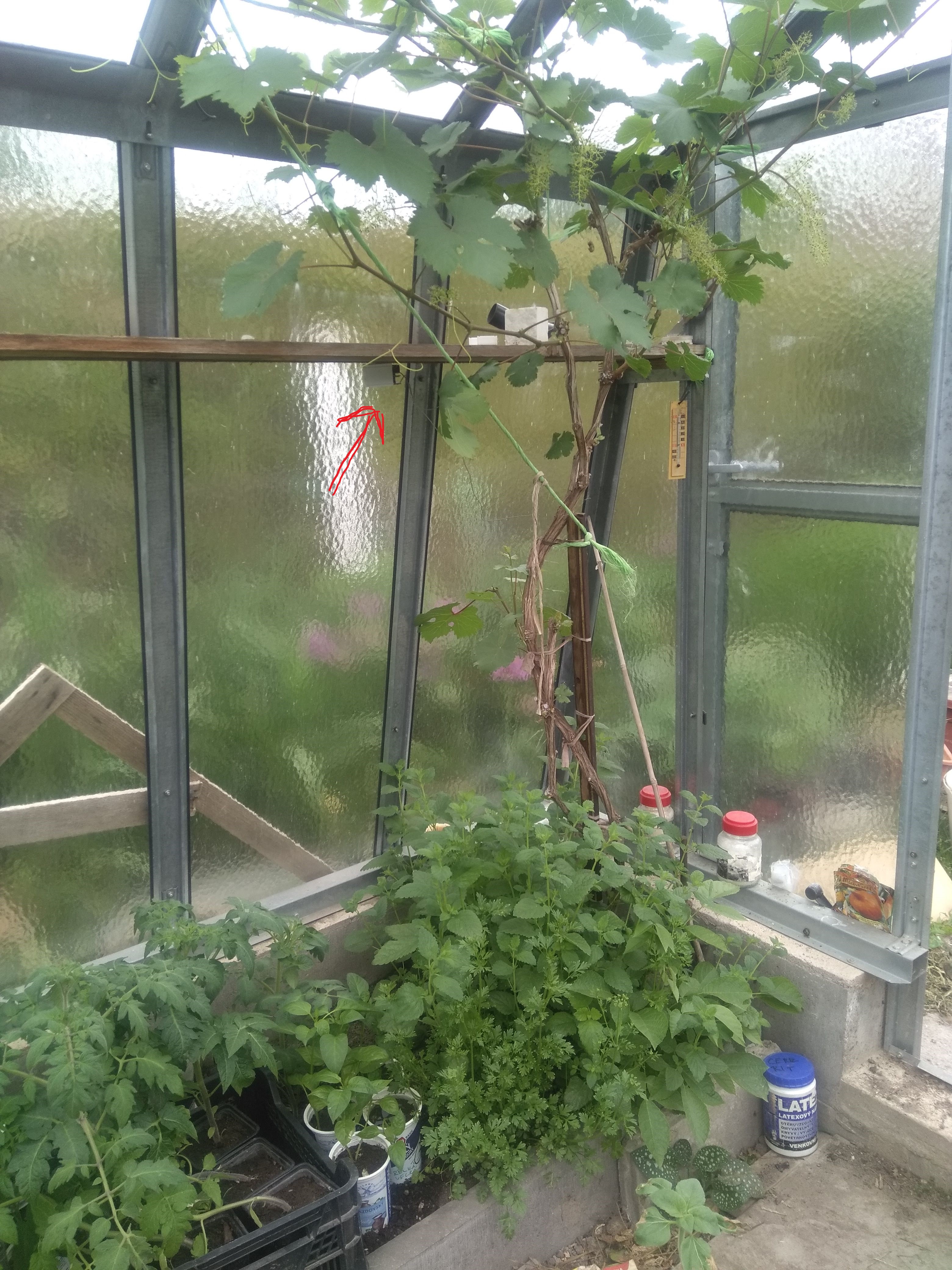
Here is photo of my situation. Climate module is in horizontal position under wooden shelf. At the beginning it was on vertical position on the floor. But signal was same. I put gateway to the vertical position because I thought that metal inside windows frame can blocks radio signal.
Hello,
did you already communicated with me about this issue? That Rpi enclosure seems bit familiar to me.
Today I tested one option. We still have a TX boost margin in SPIRIT1 radio. Default TX power is 10 dBm, but you can set it to 11.6 dBm. It is not much but it’s free and just FW update.I think that you need update only the code in the remote node, not the dongle.
You can edit file sdk/bcl/src/bc_spirit1.c and add SpiritRadioSetPALeveldBm calling that sets maximal TX value. I’ve added this loop:
    for(int i = 0; i < 8; i++)
    {
        SpiritRadioSetPALeveldBm(i, POWER_DBM);
    }
So the function looks like this:
bool bc_spirit1_init(void)
{
    if (_bc_spirit1.initialized_semaphore > 0)
    {
        _bc_spirit1.initialized_semaphore++;

        return true;
    }

    memset(&_bc_spirit1, 0, sizeof(_bc_spirit1));

    SpiritRadioSetXtalFrequency(XTAL_FREQUENCY);

    SpiritSpiInit();

    /* Spirit ON */
    SpiritEnterShutdown();

    SpiritExitShutdown();

    SpiritManagementWaExtraCurrent();

    /* Spirit IRQ config */
    SpiritGpioInit(&xGpioIRQ);

    /* Spirit Radio config */
    if (SpiritRadioInit(&xRadioInit) != 0)
    {

        bc_spirit1_hal_shutdown_high();

        bc_spirit1_hal_deinit_spi();

        bc_spirit1_hal_deinit_gpio();

        return false;
    }

    /* Spirit Packet config */
    SpiritPktBasicInit(&xBasicInit);

    SpiritPktBasicAddressesInit(&xAddressInit);

    for(int i = 0; i < 8; i++)
    {
        SpiritRadioSetPALeveldBm(i, POWER_DBM);
    }

    _bc_spirit1.desired_state = BC_SPIRIT1_STATE_SLEEP;

    _bc_spirit1.task_id = bc_scheduler_register(_bc_spirit1_task, NULL, 0);

    _bc_spirit1.initialized_semaphore++;

    return true;
}
I’ve tried to test measure TX power but I do not have proper RF equipment and my SDR sucks. But I did tested peak power consumption during transmission with uCurrent and osciloscope and I was able to see changes in peak current when I set TX power to -12 dBm (340 mA peak) to default 10 dBm (450 mA peak) to improved 11.6 dBm (470 mA peak).
Other ideas to improve signal quality could be to try to put the dongle to some USB extension coord or put it further from the window. The windows have metal frame and also metalic glass which could interfere with antenna when closer. But I’m really not an RF expert.
Another solution could be using newer version of Spirit1 module with u.Fl connector and external antenna. We still did not managed to put it in the shop, but if you are interested we can swap that for a fee.
Some info is in this thread
I’ve managed to get working RSSI indicator.
RSSI says how strong the signal is. The lower the weaker signal.
50 cm from dongle: -50 dBm
2m from dongle: -54 dBm
I was not able to compare RSSI for node FW with 10 and 11.6 dBm, the values we’re too close to say it had any advantage from few meters.
Signal is lost somewhere around -95 to -102 dBm in my case, when I’m behind many walls.
Here is the patch for SDK repository and compiled firmware for Radio Dongle.
usb-dongle-with-rssi.bin (99.3 KB) rssi.patch.txt (2.3 KB)
Now every incoming packet will create also RSSI MQTT message so you can test the position of your Dongle.
20:03:44  node/door-sensor:0/push-button/-/event-count 30
20:03:44  node/door-sensor:0/rssi -54
20:03:45  node/door-sensor:0/push-button/-/event-count 31
20:03:45  node/door-sensor:0/rssi -49
20:03:46  node/door-sensor:0/push-button/-/event-count 32
20:03:46  node/door-sensor:0/rssi -47
20:03:46  node/door-sensor:0/push-button/-/event-count 33
20:03:46  node/door-sensor:0/rssi -46.5
1 Like
Thx. I will try it. Rpi enclosure is from thingiverse. And a have never asked you about signal strength before. This is first time.
Thanks, patch applied and working as expected.
But…now I see, that signal strength is only -90dB which may explain few random gaps noticed during measurements examination ![]() Two nodes, direct distance is 8 meters through one wall between rooms… I’ll gather some rssi data for few days, then make some measurements (0.5m/2m for comparison), maybe increase TX power as you proposed and then ask for help…
Two nodes, direct distance is 8 meters through one wall between rooms… I’ll gather some rssi data for few days, then make some measurements (0.5m/2m for comparison), maybe increase TX power as you proposed and then ask for help…
My rssi during 24h
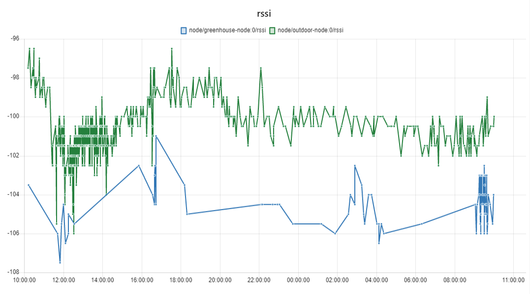
Blue line is greenhouse (50m, only glass in signal trajectory). Green is maybe 20m, but there is balcony floor and corner of garage in path.
I dont know why is greenhouse signal so bad. Because I read that signal range is up to 500m (here) and glass in path does not seems as a big problem…to me. Maybe I should try to put sensor from greenhouse in same distance but outside of greenhouse.
Note: we dont use any other device with 868Mhz.
This measurements are with default TX power? Or did you already increased TX power from 10 to 11.6 dBm as Martin suggested?
With default TX power. Next step will be to increase power.
Hi @BeranekCZ amd @kapitan-iglu
Unfortunatelly I don’t think that 11.6 dBm will be any measureable improvement, because I did not measured the big difference “on the table”.
Also someone else had signal issues in greenhouse with BigClown. I’m not an expert, but my guess is that the metal frame is doing a lot. The window in your home has most probably some metal layer on it, not sure about greenhouse glass, but usualy they are from non-metalic (makes sense, because you would like sun to shine to it).
How high above the ground is the node in the greenhouse located? Can you put it higher above the ground? Picture would help. Location would make bigger impact than software boost to 11.6 dBm.
I did that tests in open area and reached 500m. Details and video is here https://developers.hardwario.com/interfaces/sub-ghz-radio#communication-range
But that were really ideal circumstances. The test with an external antenna reached almost double range in the same spot.
Module is under a shelf (in shadow). Approximately 1.6m above land.
I tried place module outside from greenhouse. I used wire to hang it on greenhouse wall.
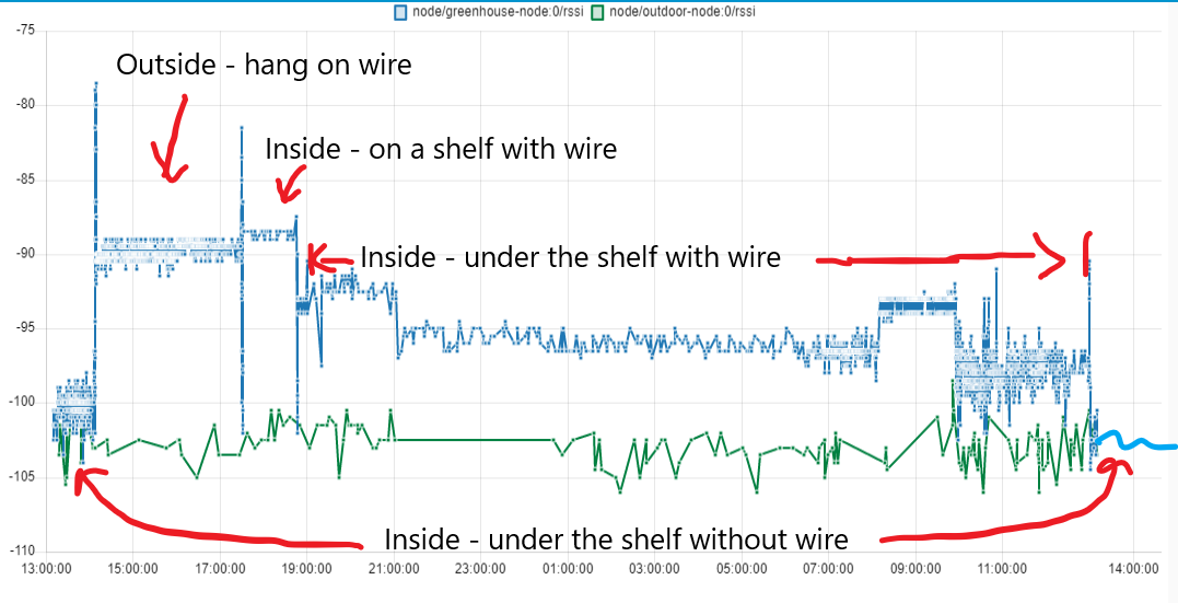
It seems that wire puted thru mounting holes in module increase signal quality.
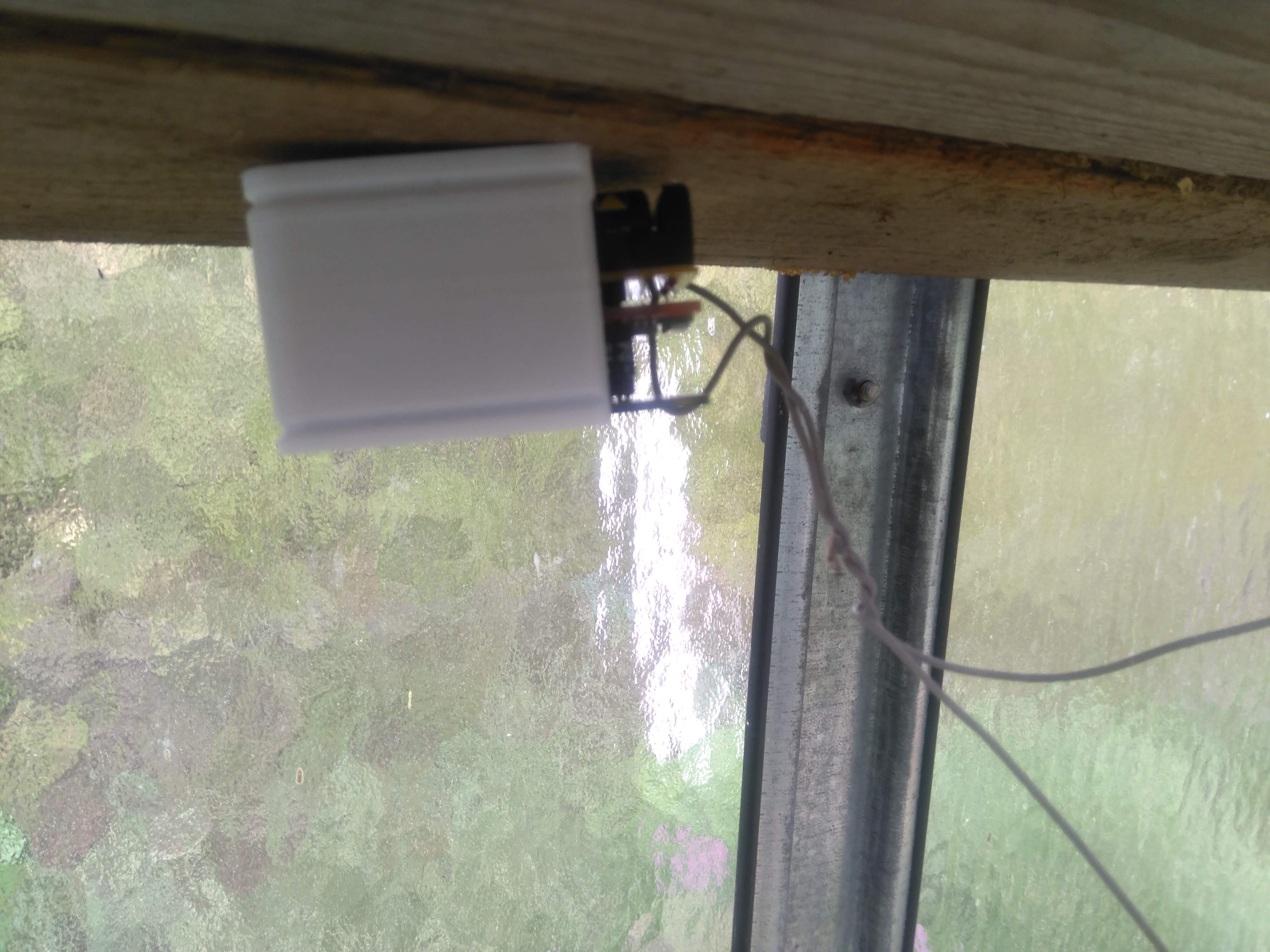
On the next picture you can see sensor position.
Is there any tutorial how to add external antenna?
We did not experimented with modification to external antenna. But now it could be possible with this RSSI measurement to remove SMD antenna and put a wire on it. Not sure if and when… but I’ll let you know if I try that.
1 Like
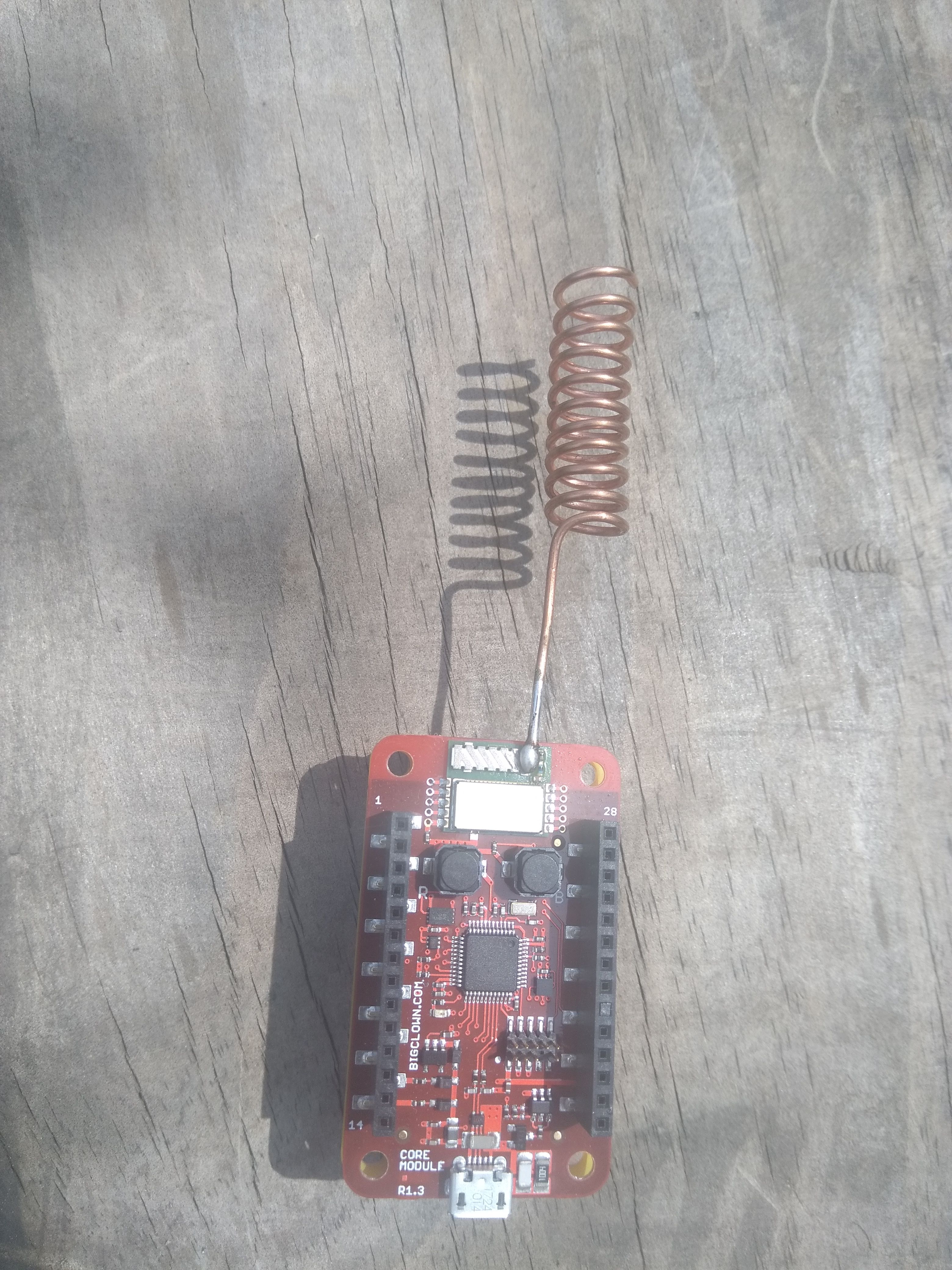
I made antenna from copper wire (spring antenna) and soldered it to smd antenna. It have better signal now(about 4dB). I have not tried remove smd antenna yet.
Two antennas in paralel is not best solution. But if it works, then why not. I would expect that if you use just the wire with the proper length (1/4 or 1/2 length of the 868 MHz wavelength) then you could get better signal. I have not tested that yet…
I know, but it was faster then remove smd antenna 
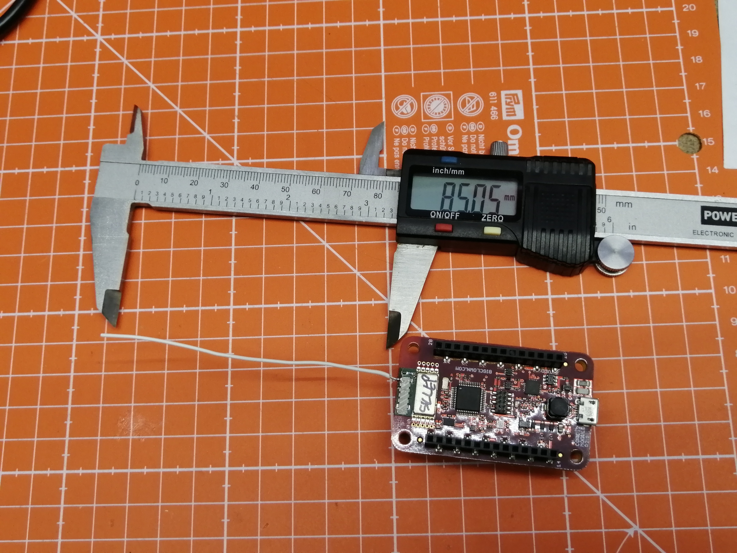
Hi, I can confirm that 85 mm wire soldered directly to antenna gained +10dBm.
When I tried to remove ceramic antenna then the signal was few dBm worse. So keeping current ceramic antenna does not seem like an issue.
2 Likes

Hi @BeranekCZ,
we have added Radio Dongle and Core Module with external antennas in our CZ/EN shop:
- https://obchod.hardwario.cz/core-module-ea/
- https://obchod.hardwario.cz/radio-dongle-ea/
- https://obchod.hardwario.cz/anteny/
In most cases you can upgrade just dongle with for example this antenna https://obchod.hardwario.cz/interni-lpwan-antena-microcoax-u-fl/ to get around 30-40% range increase based on my tests.
1 Like
Thx for information. I made an order today