Hello, I am doing this project:
But I have a problem with the led array, I’m using a bigger one and changing the values of: LED_MODULES_COUNT
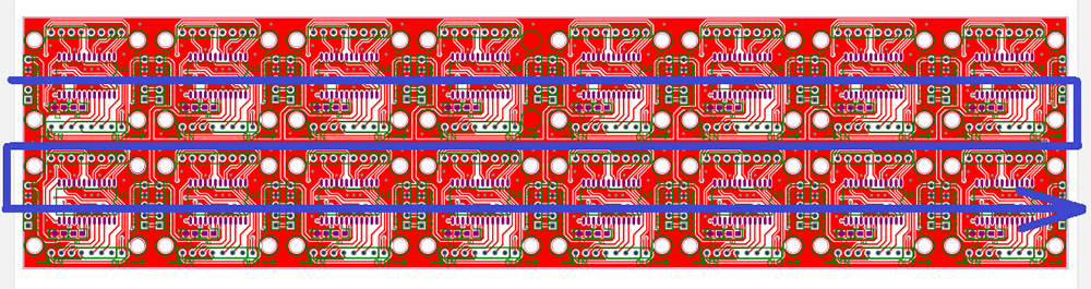
I can’t get it to work, my matrix is the one in the image is MAX7219
Thanks
Hello, I am doing this project:
But I have a problem with the led array, I’m using a bigger one and changing the values of: LED_MODULES_COUNT
I can’t get it to work, my matrix is the one in the image is MAX7219
Thanks
Hi, you need to give us more information.
Absolutely minimum is datasheet/schematics of the display module. Every manufacturer can wire them as they like. There is no “MAX7219 standard”.
Then please explain in more detail what “I can’t get it to work” means. Does it show anything? What did you tried? Can you check whether the bits you shift to the first MAX7219 does shift out correctly on next MAX7219?
Right when you turn on all the leds scroll through the screen, but when you start the script with the time, random leds turn on and they change every second, I have tried changing the number of panels but it continues to do the same (random leds).
This is the information I have: Module parameters:
Take 51 single-chip microcomputers as an example:
VCC → 5V
GND → GND
DIN → P2.2
CS → P2.1
CLK → P2.0
and the image:
“when you start the script with the time, random leds turn on and they change every second”
This is the important information I hoped for. So as I expected, every manufacturer connects MAX7219 to the row and columns differently. So the “random” LEDs are not random; they are just swapped because firmware expects different MAX7219 to LED matrix connections.
And here is the issue with every (usually Chinese) module - there are no schematics. So I can’t help you there; you have to figure out the connection yourself.
You need to edit led_matrix_draw_pixel function to match the connection on your module.
The best solution would be to create a simple loop that cycles through all 64 (8x8) pixels on the first 8x8 module. Maybe cycle it when you press the button, send the expected x,y point coordinates over console and take note of which pixel really turns on.
You must find if the rows/columns are swapped (rotated number 90 degrees) or if the pixels in the row or column are swapped between each other.
Another solution might be to find some Arduino or example code and find how the pixels are addressed, and change the led_matrix_draw_pixel accordingly.
Can you help me create the simple loop?
Create a loop in your button callback or in the application_loop()
And call clear, draw_pixel and update functions. Like in this function
You need to increment some static variable that will be incremented each time, and from this variable, with division and modulo, compute the X and Y coordinates of the pixel.
If you do this in the application_loop, then use the schedule relative function with some delay, so you can see how the pixel is moving. The TOWER doesn’t have directly delay function. It uses tasks which could be rescheduled later.
https://sdk.hardwario.com/group__twr__scheduler.html#ga3a01cc23214414434e8a981f8e98ebb3