Hello,
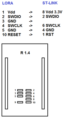
I wrote own application based on I-Cube LPWAN source and I would like to upload it to the Hardwario LORA module by ST-Link. Based on the scheme of LORA module I have connected the ST-Link to the pads on module, but the connection is not working. ST-Link told me “Can not connect to target”. Can you help me how to connect it together?
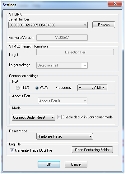
ST-Link has latest FW version and I use configuration Connect Under Reset
The reason of this is that now I would like to use the LORA module R1.4 without main Core module - only as AT_slave, which will be directly connected to the PC by UART. And default firmware included in module doesn’t support commands AT+SEND and AT+SENB
I have also tried different configurations and with/without reset signal connection, but with the same result:
Can not connect to target!
If you’re trying to connect to an STM32W1xx device, please select Normal or HotPlug mode from Target->Settings menu.
If you’re trying to connect to a low frequency application , please select a lower SWD Frequency mode from Target->Settings menu.
No target connected
P.S. The ST-Link is working without any problems - I am using it on another boards with ST’s MCU…
Hi Lukas,
I’ve checked the schematics of last revision R1.4 and the JTAG connector has the correct schematics and connection to the Murata module. I’ve cross-checked it with other of our designs where we use this module.
From R1.0 we used this JTAG to program modules, now we’ve added serial pins and program modules over serial port. So the JTAG port is not tested by programming now, it’s more like optional feature.
I’ve asked my colleagues to check that JTAG works on theirs R1.4 module to confirm it is electrically correct. I’ll let you know
You can also check schematics here
Can you power on the module and check with your voltmeter state of the pins?
VDD - 3.3V (or your power supply)
SWDIO - 3.3 V
SDIO - 0 V (low)
RESET - 3.3V
This way we can confirm that SWDIO is soldered correctly to the module. Unfortunatelly the SWCLK is low when idle. But I’ve checked wint amperemeter that if you source VDD to SWCLK pin then you get around 85 uA.
There’s one other thing. The Murata firmware locks the flash in the code itself. So first you need to unlock the protection level otherwise you couldn’t access to flash.