I would be nice and more than useful if I could find some hints to how measure 4-20 mA signal via hardwario modules.
As far as I know:
it will be necessary to make a current converter from 4-20mA to 0-3V using a resistor.
A sensor generating 4-20 mA has to be externally powered, everything else can run safely from batteries.
You’re right, the simplest solution is to use resistor to convert current to the voltage.
You have to be careful and choose the right value so the voltage across that resistor does not goes above 3 V otherwise it might destroy the GPIO pin.
On some internet articles they add zener diode with series protection resistor to make sure the voltage does exceed 3V. It also protects the pin in case your sensor looses ground, that way you have 24 V on the GPIO pin, but thanks to that serial resistor (or fuse) and zener/TVS diode, you’re safe.
If I’m not overlooking then the series resistor should be at most 150 Ohms when I count the biggest current 20 mA. The sensor voltage 12/24V does not matter.
Thanks for info about hardware setup and configuration.
==My hardware trial and questions
We (my colleague electrician, not me – clumsy one) have tried to do some simple wiring with Zener diode and appropriate resistor but we did not succeed to get right results.
My colleague sought through resources and he has found this transmitter:
We (my colleague electrician, not me – clumsy one) have tried to do some simple wiring with Zener diode and appropriate resistor but we did not succeed to get right results.
Can you explain in more detail what did you tried? Including schematics to understand what could be wrong. If you have a resistor then it must work properly, there’s nothing that could go wrong with a resistor. The zener diode is not necessary, it is more like protection in case 12 or 24 V goes to the GPIO pin when for example the ground will disconnect by some mistake.
Zener diode could be the issue if you connect it in a wrong way or choose bad value.
You can use that 4-20mA converter, but I would say it is a more complex way. With a single resistor it just works, with this converter you have to properly set jumpers and calibrate/tune the maximum voltage and offset.
If you use resitor then there is no tunning, it properly returns voltage according to current with just Ohm’s law.
Regarding the firmware there is not any project that measures voltage and sends it over radio. But documentation has this example code of asynchronous rading. Asynchronous has advantage that it also measures reference voltage and can give you exact voltage in volts (not just ADC number without any context)
So int he code uncomment the twr_adc_get_result_voltage to get voltage.
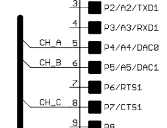
Also in the Sensor module you have channels A, B.
So for channel A you have to use ADC channel TWR_ADC_CHANNEL_A4, for B TWR_ADC_CHANNEL_A5.
However if you use the 4-20mA module, you still will need to calculate the current by some formula. It may be more complicated than plain resistor and Ohm’s law.
(we can switch to the czech language if you like, this forum is not strictly english)